
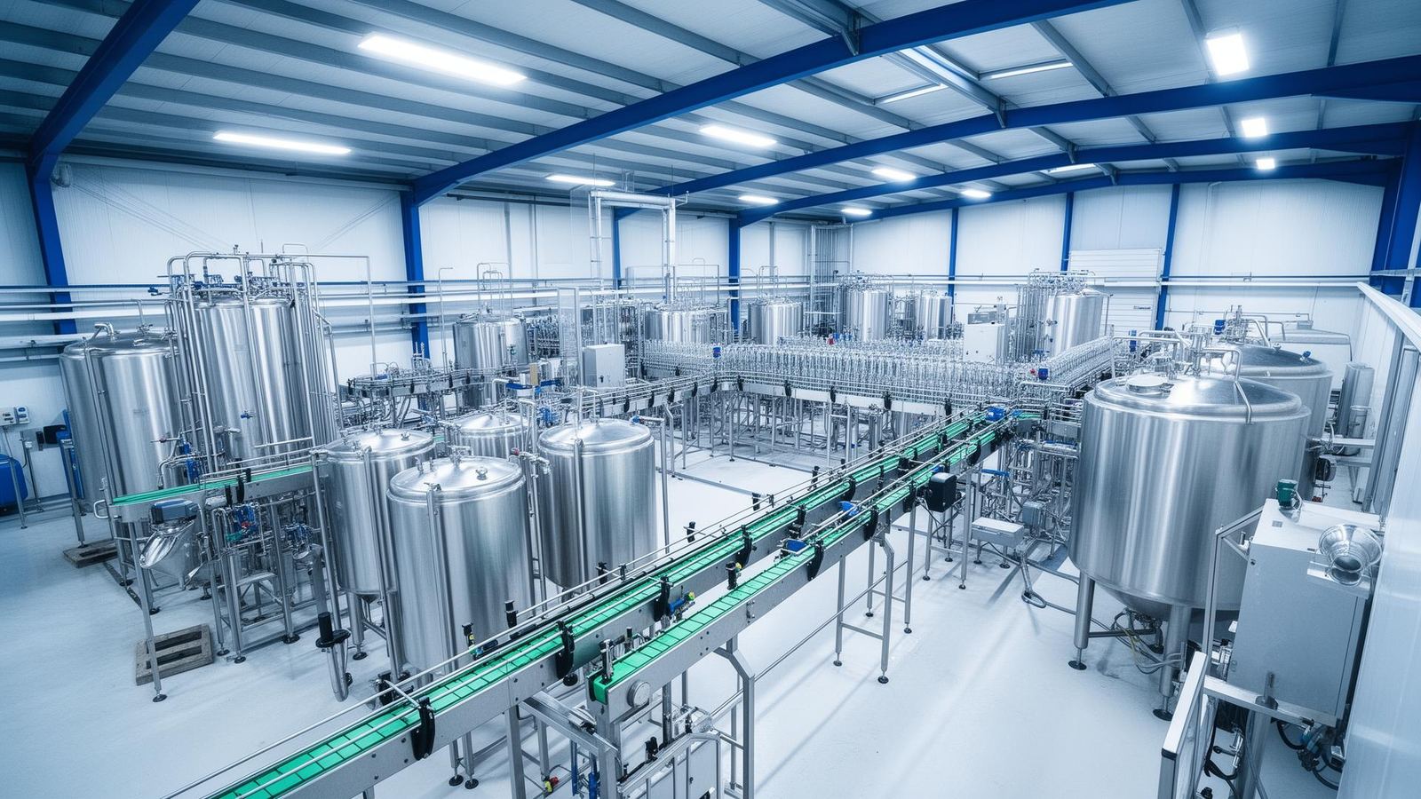
The Thermodynamic Foundation of Carbonation Control
Every carbonated beverage begins its pressurized life at the saturator discharge, where CO₂ has been forced into solution under controlled temperature and pressure conditions governed by Henry's Law. The relationship is deceptively simple in theory: gas solubility increases proportionally with pressure and inversely with temperature. In practice, maintaining that dissolved CO₂ from saturator outlet through filling valves and into a sealed container involves managing a cascade of thermodynamic transitions that even experienced plant engineers occasionally underestimate.
At 2°C and 3.5 bar absolute, water holds approximately 8.2 grams of CO₂ per liter — roughly 4.2 volumes of carbonation. Raise the product temperature by just 5°C during transfer and the equilibrium shifts enough to liberate gas that was moments ago stably dissolved. This is not a gradual process. CO₂ release follows nucleation dynamics: once bubble formation begins, the cascading effect accelerates through the fluid column. The entire philosophy of carbonated filling engineering revolves around preventing this nucleation cascade at every transition point between saturator and sealed container.
Saturator Design and Discharge Stability
Carbonation equipment falls broadly into two architectural categories: in-line carbonators that inject CO₂ into a flowing product stream through venturi or static mixer elements, and tank-based saturators where product resides under CO₂ pressure for a defined contact period. Each approach produces different discharge characteristics that affect downstream filling behavior.
In-line carbonators offer rapid response to production speed changes and occupy less floor space, but they demand precise flow metering and CO₂ injection control. If the water-to-CO₂ ratio drifts even marginally, carbonation levels fluctuate from bottle to bottle. Tank saturators provide a larger buffer volume and more stable discharge conditions, but they introduce thermal stratification risks — particularly in tanks exceeding 3,000 liters where temperature differentials between top and bottom layers can reach 1.5°C during extended production runs.
The discharge pipe routing between saturator and filler bowl deserves more engineering attention than it typically receives. Every elbow, every vertical rise, every expansion fitting creates a local pressure drop. Even a 0.2 bar transient reduction can nucleate micro-bubbles in a product saturated near its equilibrium limit. Best practice specifies gentle downward-sloping runs with large-radius bends, full-bore valves, and elimination of dead legs where product can warm during brief stoppages.
Counter-Pressure Filling Mechanics
Counter-pressure filling exists because carbonated liquids cannot be filled at atmospheric pressure without catastrophic foaming. The principle is straightforward: pressurize the container with an inert gas (typically CO₂ or filtered air) to a level approaching or exceeding the product's saturation pressure before opening the liquid valve. With the pressure differential minimized, product flows into the container without significant gas liberation.
The engineering complexity lies in the valve sequence timing. A modern isobaric filling valve executes a precise choreography: container seal against the bell or tulip, pre-evacuation of air (in some designs), counter-pressure gas injection, pressure equalization sensing, liquid valve opening, product flow by gravity or slight overpressure, level or volume sensing, liquid valve closure, snift gas release, and container lowering. Each transition involves a pressure change, and each pressure change is a potential nucleation trigger.
Valve timing tolerances measured in milliseconds separate a well-carbonated product from a foaming disaster. On a 60-valve rotary filler operating at 40,000 bottles per hour, each valve completes its full cycle in approximately 3.6 seconds. The liquid fill phase itself may consume only 1.8 seconds of that cycle. Mechanical wear in valve components — particularly the sealing surfaces of gas and liquid valves — introduces variability that compounds across thousands of cycles per hour.
Temperature sensitivity creates an additional variable. Valve bodies absorb heat from the production environment, potentially warming the first few milliliters of product contacting the valve seat. On glass fillers handling cold-filled carbonated water, condensation on valve exteriors indicates thermal gradients that subtly erode carbonation consistency.
Fobbing Dynamics and Prevention Engineering
Fobbing — the uncontrolled release of dissolved CO₂ as foam — represents the single most visible failure mode in carbonated filling operations. It wastes product, creates hygiene hazards on the filler carousel, disrupts fill level accuracy, and in severe cases forces line shutdowns for cleanup. Understanding fobbing mechanics requires thinking in terms of nucleation energy barriers.
Dissolved CO₂ exists in a metastable state within the liquid. Given sufficient activation energy — a pressure drop, a mechanical shock, contact with a rough surface — dissolved gas molecules aggregate at nucleation sites and form bubbles. Once a bubble exceeds a critical radius (determined by surface tension and local pressure), it grows spontaneously as CO₂ diffuses from the supersaturated solution into the gas phase.
Container surface quality directly influences nucleation behavior. New glass bottles with fire-polished interiors present fewer nucleation sites than returnable bottles whose surfaces carry micro-scratches from repeated washing and handling cycles. PET bottles exhibit different nucleation characteristics altogether: the polymer surface is inherently smoother but can develop static charges during air conveying that attract particulates — each particle a potential nucleation center.
Fobbing prevention operates on multiple fronts simultaneously. Product temperature management is the primary defense: colder product tolerates greater pressure transients without nucleation. Container pre-rinsing with sterile water or CO₂-enriched water reduces nucleation sites and equilibrates container temperature. Snift valve calibration — the controlled release of headspace pressure after filling — must balance between sufficient gas release for proper headspace and excessive depressurization that triggers foam. Some filling systems employ multi-stage snift sequences, releasing headspace pressure in two or three discrete steps rather than a single event, each step allowing the product to re-equilibrate before the next pressure reduction.
The Critical Transfer Zone Between Filler and Capper
A paradox of carbonated filling engineering: the most technically sophisticated machine on the line — the filler — delivers product into an open container that must travel to the capper before the seal is applied. This transfer distance, typically ranging from 0.6 meters on close-coupled monoblock designs to over 3 meters on separate filler-capper configurations, represents the interval of maximum vulnerability for carbonation retention.
During transfer, the filled container sits at atmospheric pressure or slightly above. CO₂ immediately begins migrating from the supersaturated liquid into the headspace. If the transfer time exceeds the nucleation induction period — which varies with product type, temperature, and carbonation level — visible fobbing begins before the cap is applied. Transfer conveyors that introduce vibration, sudden direction changes, or speed differentials between filler discharge and capper infeed compound the problem through mechanical agitation.
This is precisely why monoblock filling configurations dominate carbonated beverage applications. By integrating rinser, filler, and capper on a single frame with star-wheel transfers, the time between fill completion and cap application compresses to under 0.5 seconds on many designs. The mechanical synchronization is inherent — no conveyor speed matching required, no accumulation table turbulence between machines.
For installations where separate machines are unavoidable, engineers specify enclosed transfer sections purged with CO₂ atmosphere, smooth constant-velocity conveyors, and minimum-distance layouts. Some high-speed CSD lines employ pressurized transfer channels where containers travel in a controlled CO₂-enriched environment between filler and capper, though this adds significant complexity and cost.
Headspace Management and Volume Carbonation Targets
Carbonation level in the sealed container depends not only on the dissolved CO₂ concentration in the liquid but also on the headspace volume and the equilibrium pressure established after sealing. A 500 mL PET bottle filled to 440 mL with product at 4.0 volumes of CO₂ will establish a different equilibrium pressure than the same product filled to 460 mL. The 20 mL headspace difference alters the gas-liquid equilibrium and ultimately the carbonation perception by the consumer.
Fill level accuracy therefore becomes a carbonation control parameter, not merely a cosmetic or legal compliance issue. Volumetric fillers offer inherently better fill level consistency than gravity fillers for carbonated products, though electronic-controlled gravity fillers with precise snift timing can approach comparable performance on stable production runs. Weight-based filling, common in still beverage and chemical applications, finds limited use in high-speed carbonated filling because the measurement duration conflicts with the rapid cycle times required.
Temperature at the moment of sealing introduces a final variable. The product warms continuously from the moment it leaves the saturator. If the capper applies the closure with the product at 6°C rather than the intended 3°C, the equilibrium carbonation in the sealed container drops measurably. On a large CSD line producing 1,500 bottles per minute, the thermal gain between saturator and capper can represent 0.3 to 0.5 volumes of effective carbonation loss if cooling circuits are undersized or glycol supply temperatures fluctuate seasonally.
Monitoring Instrumentation and Process Control
Reliable carbonation management demands instrumentation at multiple points in the process chain. In-line CO₂ sensors positioned at the saturator discharge provide real-time dissolved gas measurement, typically using infrared absorption or conductivity-based principles. A second measurement point between the product buffer tank and filler inlet captures any carbonation loss during transfer.
Modern filling lines integrate these measurements into closed-loop control systems that adjust saturator CO₂ injection pressure and product temperature simultaneously. When the filler-inlet sensor detects a 0.1 volume drop in carbonation, the control system increases saturator pressure or reduces product temperature — or both — to compensate. Response time of these control loops determines the number of under-carbonated containers produced during a transient event.
Post-fill verification typically employs shake-test instruments or automated piercing systems that measure headspace pressure at controlled temperature. Statistical sampling rather than 100% inspection is standard, with sample frequencies ranging from every 15 minutes on stable lines to every 5 minutes during changeovers or startup phases. The measurement accuracy of these instruments — typically ±0.05 volumes — establishes the practical limit of carbonation control precision.
Pressure gauges on the filler bowl, counter-pressure manifold, and CO₂ supply line complete the instrumentation picture. Experienced operators develop an intuitive sense for normal pressure relationships across these points. When the differential between bowl pressure and counter-pressure deviates from the established baseline, they investigate before fobbing becomes visible — a diagnostic instinct that automated systems are only beginning to replicate through trend analysis algorithms.
Seasonal and Environmental Variables
Ambient temperature swings between winter and summer production periods affect carbonation management more than many plant managers acknowledge. A facility operating in a Mediterranean climate may see ambient temperatures range from 8°C in January to 38°C in August. Product cooling capacity that comfortably maintains 3°C discharge temperature in winter may struggle to hold 5°C during peak summer — a 2°C difference that shifts the entire carbonation equilibrium.
Glycol chiller sizing for carbonated filling applications should account for worst-case ambient conditions plus a safety margin. The cooling load calculation must include not only the product stream but also heat gain through pipe insulation, filler bowl thermal mass during startup, and radiant heat from lighting and adjacent equipment. Undersized cooling systems force operators to reduce line speed during hot weather, directly impacting production throughput and delivery schedules.
Incoming water quality presents seasonal variation as well. Source water temperature, mineral content, and dissolved oxygen levels change with the seasons and affect both carbonation chemistry and equipment fouling rates. Higher dissolved oxygen competes with CO₂ for dissolution sites in the product and accelerates corrosion of stainless steel wetted parts operating under carbonic acid conditions. Water treatment systems upstream of the saturator must accommodate these fluctuations without introducing their own variability into the process.
Altitude is a fixed but often overlooked environmental variable. Plants located above 500 meters experience reduced atmospheric pressure that lowers the effective counter-pressure baseline. A filling valve calibrated at sea level will under-pressurize containers at elevation, potentially allowing fobbing that would not occur at the original commissioning site. Relocated equipment requires recalibration of all pressure setpoints to account for the new atmospheric reference.
Frequently asked questions
What determines CO₂ retention during counter-pressure filling?
CO₂ retention depends on the equilibrium between dissolved gas pressure, product temperature, headspace volume, and the differential between saturation pressure and counter-pressure applied in the filling valve. Maintaining product temperature below 4°C and minimizing pressure differentials during valve transitions are the primary engineering controls.
Why does fobbing occur in carbonated beverage filling?
Fobbing results from sudden CO₂ liberation when dissolved gas exceeds the saturation limit at a given temperature and pressure. This typically happens during pressure transitions in the filling valve, at the snift station, or during container transfer between filler and capper. Nucleation sites on container surfaces accelerate the effect.
What is the role of snift pressure in carbonated filling?
Snift pressure is the controlled release of headspace gas after filling to reach the target carbonation volume. Incorrect snift timing or excessive depressurization causes violent fobbing and product loss. Engineers calibrate snift to reduce headspace pressure gradually while maintaining enough CO₂ in solution.
How does product temperature affect carbonation levels?
CO₂ solubility in water increases as temperature decreases, following Henry's Law. At 2°C, water can dissolve approximately 8.5 g/L of CO₂ at atmospheric pressure. At 20°C, this drops to roughly 3.5 g/L. Maintaining cold chain integrity from saturator to sealed container is therefore critical for carbonation retention.
What carbonation volumes are typical for different beverages?
Carbonation levels vary by product: still water contains 0 volumes, lightly sparkling water 1.5–2.5 volumes, beer typically 2.4–2.8 volumes, soft drinks 3.0–4.5 volumes, and sparkling wine 5–6 atmospheres. Each requires different saturation and filling pressure profiles.